danemania1
Hasn't posted much yet...
Warning. Do this at your own risk. I accept no responsibility if you damage your vehicle.
This is just a reference that I did to my vehicle.
This mod will light up the LED strips as DRL while your switch is on auto. The amber lights will be off When the parking lights or headlights come on the led strip dims , when the blinker is on the amber light will flash and so will the led strip. ( at a later date I will add info on how to have the led light go out while the blinker is on.
Tools and supplies
panel tool
8mm 10mm 12 mm sockets and ratchet with extension
Phillips head screw driver
razor blade
wire 3 colors
wire ties
wire strippers and cutters
4 sets of waterproof wire connectors (something that can be disconnected and re connected)
tube of silicon
in line fuse holder and 10 amp fuse
2 SPDT relays and harness or female blade connectors 20 amp minimum ( auto parts store or ebay)
3M super 33+ electrical tape (Home Depot)
drill with bit about the size of 22 guage wire
recommended : solder and soldering iron.
I think thats it
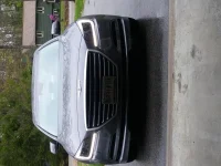
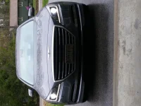
you will need to remove the headlights and to do that you need to remove the front bumper cover
it actually comes off fairly easy.
View attachment 12063
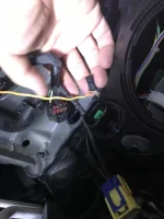
Remove the headlights and on the bottom there is a round access panel. Turn it and remove. This will give access to the wires on the LED board. There is a harness with 3 locations and only 2 wires.
View attachment 12064
Your going to add a wire to the blank spot. I do not have access to the factory harness pins on this harness or the headlight connector so here is what to do. Drill a small hone next to the factory headlight connector just big enough to insert a wire about 22 guage. Run the wire in the light assembly and tin the end (strip the wire and coat with solder) this will give it rigidity. Unplug the 2 pos harness and insert the new wire.
View attachment 12065
Tape it and wire tie it to the other 2 wires so it doesn't pull out and re connect the wire.
View attachment 12066
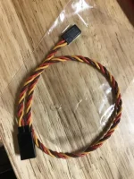
On the end outside the light assembly connect half of one of the waterproof wire connectors.and then add a wire tie to the wire on the inside of the assembly to keep it from pulling out. silicon the hole you drilled to seal it. set lights aside to let the silicon dry
View attachment 12067
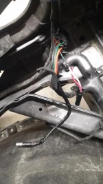
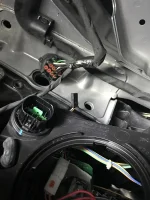
now inside the car you will need to remove the lower dash panel covering the wires at the fuse box you will need to run wires 3 of them from the fuse box to under the hood near the brake fluid fill. near the firewall on the drivers side.
At the fuse box you will see this harness

on the 4 pin harness the thick wires. The wire on the left (red) is BATT. Connect the in line fuse leave the fuse out for now. Connect a length of wire to the other end of the in line fuse holder.
The other 2 wires are for the left and right blinker. The one on the left is for the right blinker and the one to the right is the left blinker.
Do not use scotch lock type of wire taps. They will fail and look awful. Use wire strippers and make a cut in the insulation in 2 spots about a ¼ inch apart and using a razor blade slice between the cuts and remove the section of insulation exposing a section of bare copper. Wrap your stripped new wire around and solder and tape. If no solder just wrap tight and tape.
There is a grommet in the firewall to the left of the brake pedal. You will need to run the wires to this grommet. Using a razor blade cut a slit in the grommet at the indentation near the top. You will need to slide a snake through the grommet. A long wire tie 3ft or so (Home depot) with the end cut off works well. Keep moving is and out until you can get to the other end under the hood. Its tight in there so it may take some time. Tape the wires to the snake, put a drop of dish detergent or soap on the wire where its tapped and it will slide right through.

These will now wire to the relays. The reason for the relays is the blinker lights were wiring into are for the rear and we want to isolate them and it will also prevent any more current on the circuits. I made a little bracket to mount the relays but you can just wire tie them to a harness
View attachment rh headlight.pdf
On the bottom of the relays there are 5 tabs with numbers next to them

label the relays left and right
wire both tabs 85 to ground
wire both tabs 87 to the BATT wire you ran
tab 87a is not used
tab 86 on left relay goes to the left blinker wire you ran
tab 86 on right relay goes to the right blinker wire you ran
tab 30 on left relay goes to the left headlight
tab 30 on the right relay goes to the right headlight.
Run 2 wires from tabs 30 to the left headlight and continue the right side wire across the front of the car following existing harnesses to the right headlight.. these wires should be covered in loom and can be run under the beauty cover near the left fender. Wire tied to the hood pop cable.
now install the headlights
At the headlights you need to find pin 10 and cut it
View attachment rh headlight.pdf
On the side of the wire toward the car connect the other half of the waterproof connector you wired to the headlight and connect them together. Install another waterproof connector on the light side of the wire you cut and to the blinker wire you ran and connect them. Do this for both headlights.

Put the fuse in the fuse holder and test, be sure its bright enough for the DRL to be on .
And test, if they're not working check all your connections. You will hear the relays clicking when the blinkers are on. This is normal.
Tape up the wiring at the relays and loom or tape all exposed wiring and secure with wire ties
if for some reason you want to put it back to the way it was just reconnect the wires on pin 10 with the waterproof connectors you installed and pull the fuse out.
reassemble your car
this is the first write up Ive ever done so I hope I didn't miss anything
let me know if you have questions
This is just a reference that I did to my vehicle.
This mod will light up the LED strips as DRL while your switch is on auto. The amber lights will be off When the parking lights or headlights come on the led strip dims , when the blinker is on the amber light will flash and so will the led strip. ( at a later date I will add info on how to have the led light go out while the blinker is on.
Tools and supplies
panel tool
8mm 10mm 12 mm sockets and ratchet with extension
Phillips head screw driver
razor blade
wire 3 colors
wire ties
wire strippers and cutters
4 sets of waterproof wire connectors (something that can be disconnected and re connected)
tube of silicon
in line fuse holder and 10 amp fuse
2 SPDT relays and harness or female blade connectors 20 amp minimum ( auto parts store or ebay)
3M super 33+ electrical tape (Home Depot)
drill with bit about the size of 22 guage wire
recommended : solder and soldering iron.
I think thats it
you will need to remove the headlights and to do that you need to remove the front bumper cover
it actually comes off fairly easy.
View attachment 12063
Remove the headlights and on the bottom there is a round access panel. Turn it and remove. This will give access to the wires on the LED board. There is a harness with 3 locations and only 2 wires.
View attachment 12064
Your going to add a wire to the blank spot. I do not have access to the factory harness pins on this harness or the headlight connector so here is what to do. Drill a small hone next to the factory headlight connector just big enough to insert a wire about 22 guage. Run the wire in the light assembly and tin the end (strip the wire and coat with solder) this will give it rigidity. Unplug the 2 pos harness and insert the new wire.
View attachment 12065
Tape it and wire tie it to the other 2 wires so it doesn't pull out and re connect the wire.
View attachment 12066
On the end outside the light assembly connect half of one of the waterproof wire connectors.and then add a wire tie to the wire on the inside of the assembly to keep it from pulling out. silicon the hole you drilled to seal it. set lights aside to let the silicon dry
View attachment 12067
now inside the car you will need to remove the lower dash panel covering the wires at the fuse box you will need to run wires 3 of them from the fuse box to under the hood near the brake fluid fill. near the firewall on the drivers side.
At the fuse box you will see this harness
on the 4 pin harness the thick wires. The wire on the left (red) is BATT. Connect the in line fuse leave the fuse out for now. Connect a length of wire to the other end of the in line fuse holder.
The other 2 wires are for the left and right blinker. The one on the left is for the right blinker and the one to the right is the left blinker.
Do not use scotch lock type of wire taps. They will fail and look awful. Use wire strippers and make a cut in the insulation in 2 spots about a ¼ inch apart and using a razor blade slice between the cuts and remove the section of insulation exposing a section of bare copper. Wrap your stripped new wire around and solder and tape. If no solder just wrap tight and tape.
There is a grommet in the firewall to the left of the brake pedal. You will need to run the wires to this grommet. Using a razor blade cut a slit in the grommet at the indentation near the top. You will need to slide a snake through the grommet. A long wire tie 3ft or so (Home depot) with the end cut off works well. Keep moving is and out until you can get to the other end under the hood. Its tight in there so it may take some time. Tape the wires to the snake, put a drop of dish detergent or soap on the wire where its tapped and it will slide right through.
These will now wire to the relays. The reason for the relays is the blinker lights were wiring into are for the rear and we want to isolate them and it will also prevent any more current on the circuits. I made a little bracket to mount the relays but you can just wire tie them to a harness
View attachment rh headlight.pdf
On the bottom of the relays there are 5 tabs with numbers next to them
label the relays left and right
wire both tabs 85 to ground
wire both tabs 87 to the BATT wire you ran
tab 87a is not used
tab 86 on left relay goes to the left blinker wire you ran
tab 86 on right relay goes to the right blinker wire you ran
tab 30 on left relay goes to the left headlight
tab 30 on the right relay goes to the right headlight.
Run 2 wires from tabs 30 to the left headlight and continue the right side wire across the front of the car following existing harnesses to the right headlight.. these wires should be covered in loom and can be run under the beauty cover near the left fender. Wire tied to the hood pop cable.
now install the headlights
At the headlights you need to find pin 10 and cut it
View attachment rh headlight.pdf
On the side of the wire toward the car connect the other half of the waterproof connector you wired to the headlight and connect them together. Install another waterproof connector on the light side of the wire you cut and to the blinker wire you ran and connect them. Do this for both headlights.
Put the fuse in the fuse holder and test, be sure its bright enough for the DRL to be on .
And test, if they're not working check all your connections. You will hear the relays clicking when the blinkers are on. This is normal.
Tape up the wiring at the relays and loom or tape all exposed wiring and secure with wire ties
if for some reason you want to put it back to the way it was just reconnect the wires on pin 10 with the waterproof connectors you installed and pull the fuse out.
reassemble your car
this is the first write up Ive ever done so I hope I didn't miss anything
let me know if you have questions